| Data Model |
[This is preliminary documentation and is subject to change.]
This chapter describes the data model (tables, relationships between tables, etc.) in the database.
Two different notations are used to describe the data model:
Logical data model diagrams: UML class diagrams
Physical data model diagrams: E-R (=Entity-Relationship) diagrams
"Logical" data model diagrams use a subset of the UML class diagram notation.
There is not necessarily a 1:1 relation between boxes in the diagram (in UML notation: classes) and database tables.
The diagrams may describe features, that cannot be expressed in relational databases (e.g. generalization/specialization, also called inheritance).
The purpose of a logical data model diagrams is to give an overview of (part of) the data model, ignoring many of the techical details. For example, fields / properties are generally not displayed in the logical data model diagrams.
To understand logical data model diagrams, the reader should be familar with the UML class diagram notation. It may be necessary to consult the accompanying explanation in order to "map" between classes in the UML diagrams and database tables in the physical data model (see below).
"Physical" data model diagrams describe the actual database tables - and the relations between them - in Entity-Relation (E-R) diagrams.
A "box" in an E-R diagram is called an Entity, and an arrow is called a Relation. Relationships in relational databases are realized by "foreign keys" - i.e. one table contains fields that refer to key fields in other tables.
There is a 1:1 relationship between entities in the E-R-diagram and a physical database table.
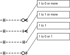
Relations in the E-R diagrams use the "crow's foot" notation:
The standard tool to get information from relational databases is SQL. In TOPICA - like in almost every application using relational database systems - SQL is used for every task involving getting data out of (or into) the database, e.g.:
Knowledge of the physical data model is important for the following roles:
Configurator - when developing reports etc.
Application Developer - for developing interfaces to external systems, etc.
Framework Developer - when modifying the static data model when developing new versions of the framework.
The Static Data Model holds the information handled by the standard functionality in the framework (organization / user / patient management, security, accreditation). It also holds metadata (in the Data Dictionary) that describes the Dynamic Data Model
The cenral idea in TOPICA - and where it distinguishes itself from most other systems - is, that the physical data model for storing patient record data is generated dynamically (at run time) from the configuration items (structure file and forms) that the configurator designs.
Therefore, the actual data model used in any particular application / database cannot be described here. Instead, the framework (the web application) contains functionality to browse the Dynamic Data Model.
Obviously, the static and dynamic parts of the data model are connected. This logical data model diagram shows how (simplified):
The classes OrgUnit, Employee, Patient and LogEntry are the most important in the static data model. Each of these correspond to a database table - they appear in various physical data model diagrams (E/R-diagrams).
The class Record does NOT correspond to a (single) database table. Record is a superclass, representing all the database tables in the dynamic data model. Each configured form generates one table in the database (forms containing arrays generate one additional table per array).
Note that Record has an "auto-relation" (one record may contain N subrecords). This illustrates, that the dynamic data model is hierarchical. A configurator designs a system of forms with subforms, which may have further subforms - in arbitrary number of levels.